 Polski
 English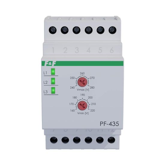
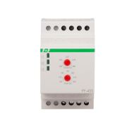
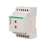
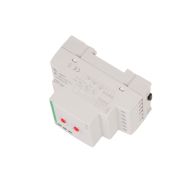
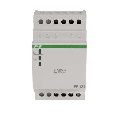
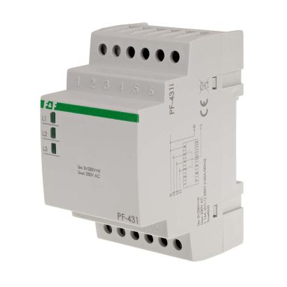
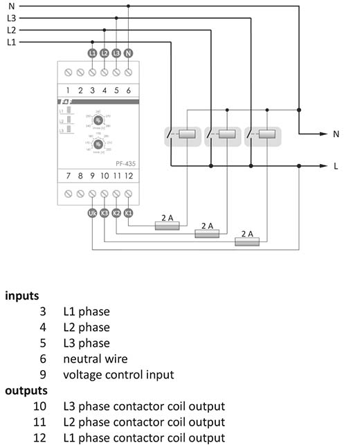
For cooperation with contactor
Without priority phase
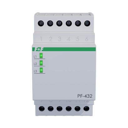
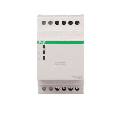
With regulation
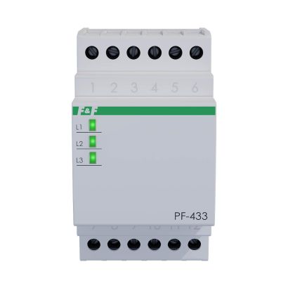
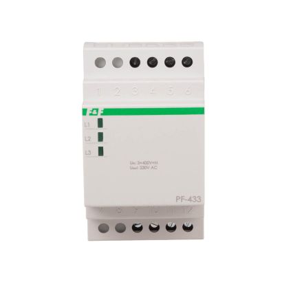
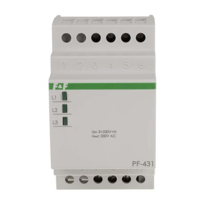
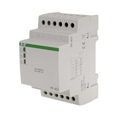
The PF-435 TRMS automatic phase switch is designed to maintain a continuous power supply to a single-phase load in the event of a phase failure or if the phase exceeds the set parameters. The device’s compact size saves space in the electrical cabinet.
The device measures the true root mean square (True RMS) voltage, making it ideal for use in modern automation systems, where the supply voltage is often distorted due to the operation of nearby devices with switching power supplies.
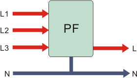
Operation of the PF-435 TRMS phase switch
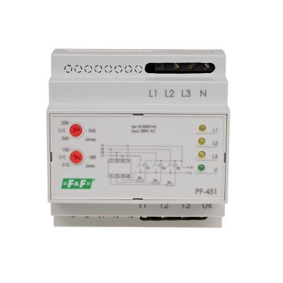
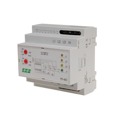
Three-phase voltage (3×230 V+N) is connected to the unit’s input terminals. A single-phase voltage (230 V) from one of the phases appears at the relay output. The switch’s electronic circuit monitors the voltages of the input phases to ensure that the output voltage is neither lower nor higher than the set values. The phase with the correct parameters is routed to the switch’s output.
The device measures the true RMS voltage, making it ideal for use in modern automation systems, where the supply voltage is often distorted due to the operation of nearby devices with switching power supplies. A green LED lights up to indicate that the relevant phase has been switched to the switch output. All phases have the same priority, which means that the first valid phase will be connected to the output (after power-up, the check begins with phase L1). The output phase will only be changed if the output voltage falls outside the range of 207–253 V. If the output phase voltage is 10 V below 207 V, or 10 V above 253 V, the switchover will occur with a 10-second delay. If a phase falls outside this range, it will be disconnected immediately (approximately 200 ms).
In both cases, if the voltage of any phase is outside the correct range,the output load is disconnected. It is not possible to switch the output to a phase with incorrect parameters.
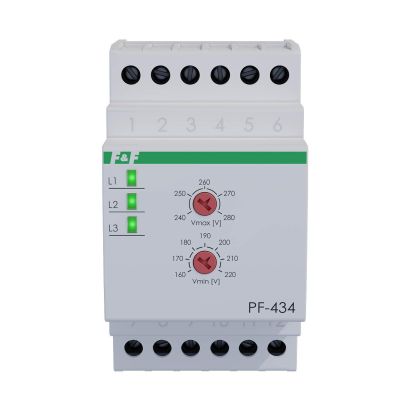
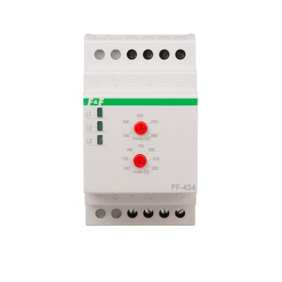
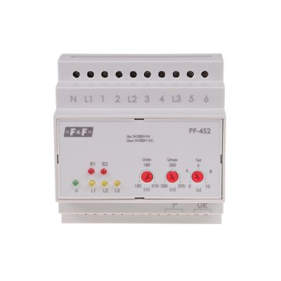
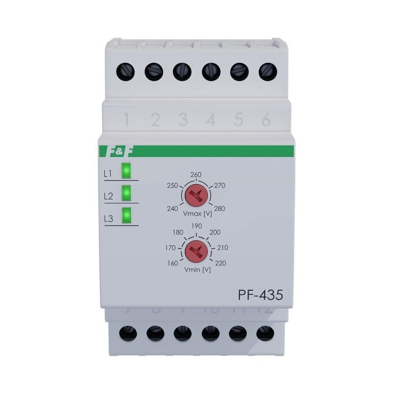
The operating voltage range for all three phases is set using the Vmax and Vmin knobs. The Vmax knob sets the maximum permissible output voltage, whilst the Vmin knob sets the minimum voltage. If the phase voltage lies between the Vmin and Vmax thresholds, it is considered to be within the correct range. In addition, the device features a monitoring contact used for continuous monitoring of the output status. This enables the detection of anomalies such as a stuck contact in one of the contactors or a faulty contact. If, after all contactors have been switched off, the output voltage remains above 20 V for longer than 1 s, all LEDs will start to flash. The relevant contactor will only be switched on once the voltage drops below 20 V. If the voltage drop lasts for less than 1 s, the LEDs will not start flashing. This protection feature detects any stuck contacts in the contactor or prevents the contactor from being switched on if the output voltage is generated externally. If the contactor for the selected phase is energised and the output voltage is at least 10 V lower than the input voltage after 1 second, the contact is deemed to be faulty. That phase is deactivated until the voltage on the device has completely dropped to zero (reset). This situation is indicated by the LED for the faulty phase flashing. If the device detects that all 3 contactors are faulty, it will attempt self-repair and, after 60 s, all outputs will be deemed operational. If the situation persists and none of the contacts are operational, all outputs will be disabled until the supply voltage drops to zero.

For cooperation with contactor
Without priority phase
With regulation