Polski
 English


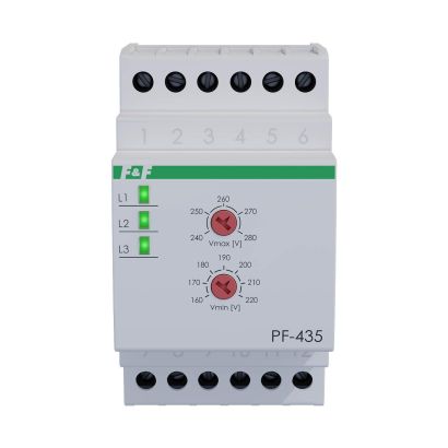
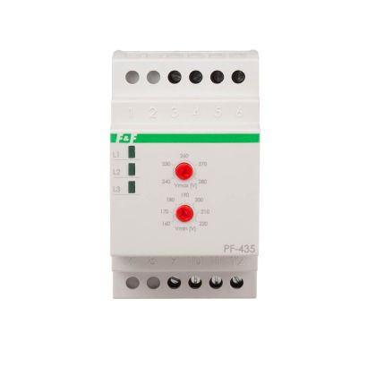
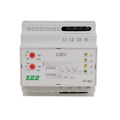
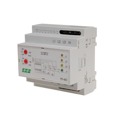
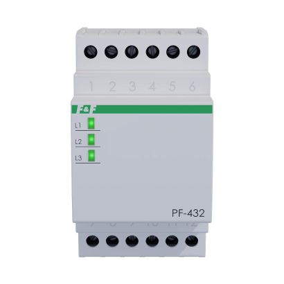
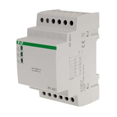
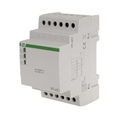
With "Priority" phase. For co-operation with contactors.
Automatic phase switches serve to maintain continuity of power supply to single-phase receivers in the event of power phase decay or a drop in its parameters below standard values.
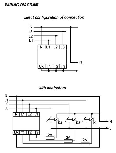
Functioning
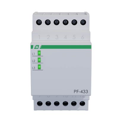
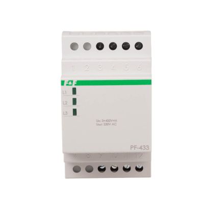
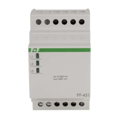
The directly connected switch is used for supplying the single-phase circuit whose current-load does not exceed 16A. For the circuits that have a current-load higher that 16A, a configuration is used that consists of a switch and three contactors that have a properly selected current-carrying capacity. Three-phase voltage (3x230V+N) is supplied to the input of the switch (L1, L2, L3, N). Single-phase voltage (230V AC), i.e. the phase voltage of one of the phases, is directed to the output of the switch (T1, T2, T3). The electronic system of the switch controls voltage values of the phases supplied. The phase that has correct parameters is switched to the output of the switch. The L1 phase is the priority phase, i.e. if its parameters are correct, this phase will be always switched to the output. If the voltage parameters of the L1 phase are not correct or if voltage decay occurs in this phase, the electronic system will switch the L2 phase to the output (provided that its parameters are correct). In case of a simultaneous lack of correct voltages in the L1 and L2 phases, the L3 phase will be switched to the output. When the correct supply voltage returns to the L1 phase, the electronic system will switch this phase to the output. The switch-over time (required for voltage to occur at the output) after the decay of a currently activated phase is from 0.5 to 0.8 sec. (during this time the receivers are not supplied). Uk input is used for controlling the voltages activated. The system enables the activation of only one phase. In this way the simultaneous switching of voltages of two phases to the output is prevented. Such simultaneous switching of voltages might lead to a phase-to-phase fault. Also, the defect of the contactor (for example, a break in the coil circuit, suspending or burning out of the working contactor) will cause the switching of the receiver to another phase despite the fact that the voltage in a given phase is correct. If the contacts of the contactor are permanently closed, the system will not switch to another contactor despite the fact that the voltage in this phase is incorrect. After the activation of supply voltage (at least one phase), the system examines the correctness of voltages supplied for 2 seconds and only after that time the system switches the phase to the output.


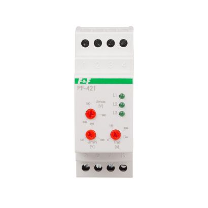
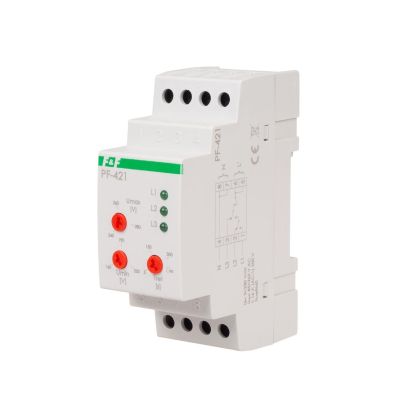
With "Priority" phase. For co-operation with contactors.
Automatic phase switches serve to maintain continuity of power supply to single-phase receivers in the event of power phase decay or a drop in its parameters below standard values.