Polski
 English


Application of the PF-421 TRMS automatic phase switch
The PF-421 automatic phase switch is used to maintain the continuity of the power supply of a single-phase receiver in case of phase failure or when the phase exceeds preset parameters. The compact size of the device allows you to save space in the electrical cabinet.
By measuring the RMS value of the voltage (True RMS), the switch guarantees the correct operation even when operating with a severely disturbed power supply network.
Functioning
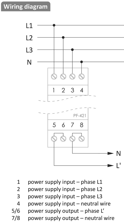
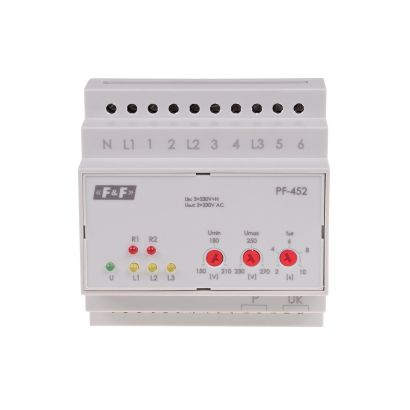
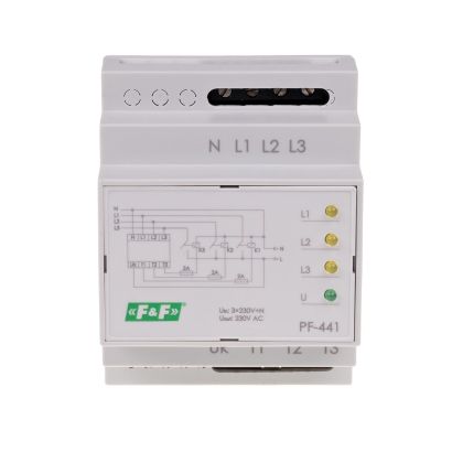
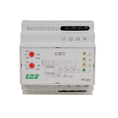
A three-phase voltage (3×230 V+N) is connected to the input terminals of the device. A single-phase voltage (230 V) of one of the phases appears at the output of the relay. The electronic circuit of the switch controls the voltage values of the supplied phases so that the output voltage is not lower or higher than the set values. The phase with the correct parameters is directed to the output Switch. The device measures the RMS value (True RMS) of the voltage, so it is perfect for modern automation systems, where the supply voltage is often distorted due to the operation of nearby devices with pulse power supplies. The corresponding green LED light indicates that the phase is connected to the output of the switch. Depending on the set mode of operation, phase L1 is the priority phase, or the system operates without phase priority (Tret set to ∞ ).
Operating with the priority phase
In this mode, the L1 phase is the priority phase and if its parameters are correct for the time set by the Tret knob, it will be connected to the output. If the L1 phase exceeds the upper or lower settings level (its voltage value will be incorrect), then the voltage of the L2 phase (if it has the correct parameters) will be connected to the output, or the L3 phase, if the L2 phase was also incorrect. If phase L3 is connected to the output and phase L2 returns to the correct parameters, and will be correct for the time set by the Tret knob, then it will be switched to the output (priority of phases from highest to lowest is L1, L2, L3). If the output phase voltage is 10 V below the set value or 10 V above it, the switchover will occur with a 10-second delay. If the phase value goes beyond this range, it will be disconnected immediately (about 200 ms).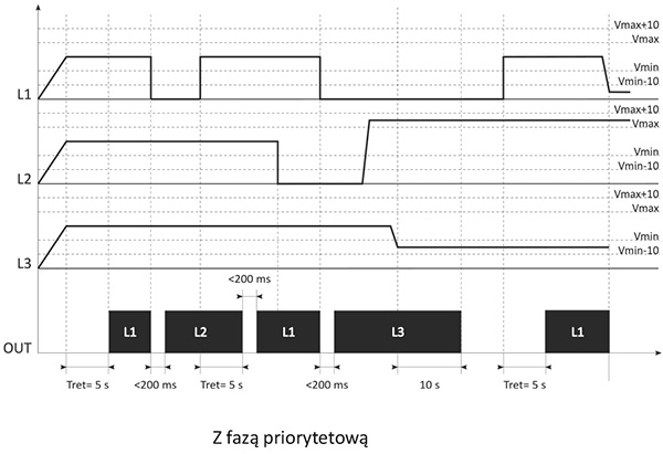
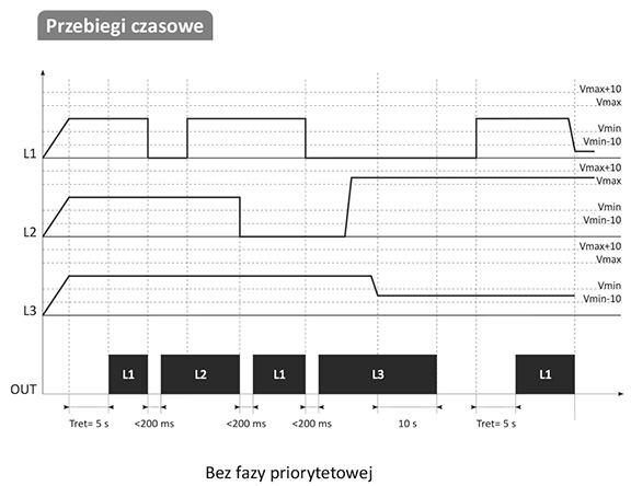
Operating without the priority phase (Tret set tos ∞ ).
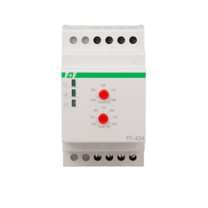
In this mode, all phases have the same priority, which means that the first of the correct phases will be connected to the output (when the power is switched on, the check starts from phase L1). The output phase will be changed only when the voltage at the output exceeds the range set by the Vmin and Vmax knobs. If the output phase voltage is 10 V below the set value or 10 V above it, the switchover will occur with a 10-second delay. If the phase value goes beyond this range, it will be disconnected immediately (about 200 ms). In both cases, when the voltage of either phase is not in the correct range, the output load is disconnected. Switching the output to a phase with incorrect parameters is not possible. The operating voltage range for all three phases is set using the Vmax and Vmin knobs. The Vmax knob determines the maximum allowable output voltage, while Vmin determines the minimum voltage. If the phase voltage value is between the Vmin and Vmax thresholds, it is considered normal.
Incorrect connection of the input wires (N connected in the wrong place) will switch the leads at the output, which means that in the place where the N potential should appear the phase voltage connected to the N input terminal will appear. The N potential will appear where the potential of the selected phase should appear. If the voltage of the phase connected to the N terminal is incorrect, the output will be completely disconnected, but the potential of the incorrectly connected phase will still be present at the output!