Polski
 English

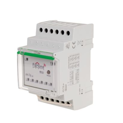
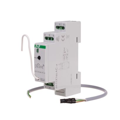
Module for integration with alarm systems of the F&Home RADIO system.
The rH-AC15R4S4 module is designed for integration with alarm control units of any manufacturer. It has 15 high-resistance analog inputs, four low-voltage relay outputs and four 5 - 10 V optocoupler inputs. Communication with the server is done by radio. The module performs a measurement of voltage on analog inputs and compares the value of that voltage with the reference voltage. Any deviation of more than 0.6 V up or down compared to the reference voltage is treated as a state of excitation and logical state „1” is generated on the output. With deviation lower than 0.6 V the output of a compactor assumes logical state „0”. The reference voltage is treated as a voltage of inactive state (logical state „0” on the output). The state of compactor is indicated by a LED placed at each input. If the compactor output logical state is „1” the LED is lighted. The value of the reference voltage for each input individually is measured and stored for all inputs simultaneously after pressing CAL button. With reference voltage value saved it can cooperate with any voltage range of motion sensors. Relays and contact inputs operate in the same way as in the module rH-R3S3 (without the autonomous mode).
The rH-AC15R4S4 module is represented by an object that is composed of 15 output channels on which the comparison result appears in binary form. The comparison of input voltage with reference voltage is done in the, individually for each channel. By deviating from the reference voltage by less than +/-0,6 V, the logical state „0” is generated on the corresponding output. Larger deviation causes that the logical state „1” is generated on the corresponding output.
The module is also equipped with four binary inputs and four binary (bi-state) outputs of the relay, separate for each physical input. Input of the object is used for controlling the channels of the relay, and the information about current operational state of the given channel of the relay is passed to the output. Four consecutive entries are used for direct changing of the logical status on appropriate outputs by closing or opening the contact. In addition, the module has byte output "Error code", which has a value of '1' if the object loses connectivity with the module. As soon as the transmission is unlocked the signal returns to ' 0 '.


Module for integration with alarm systems of the F&Home RADIO system.