Polski
 English


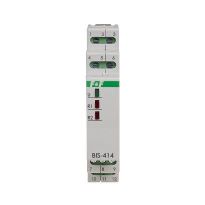
Functioning
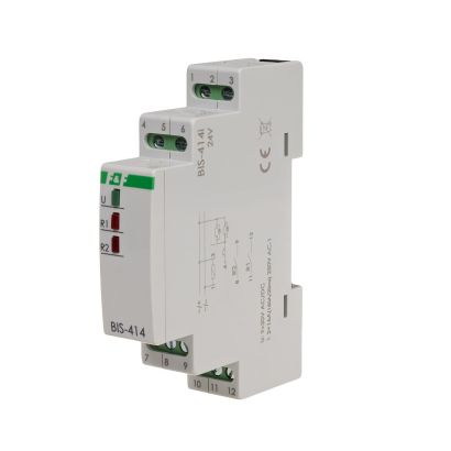
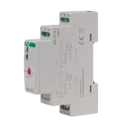
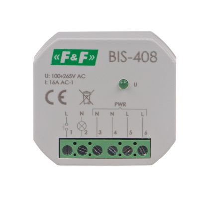
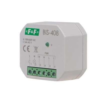
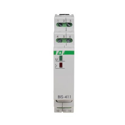
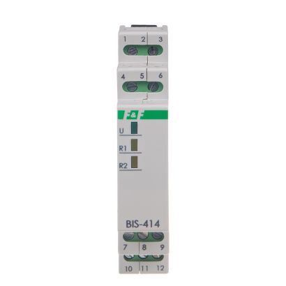
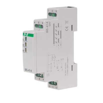
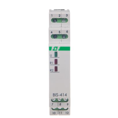
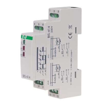
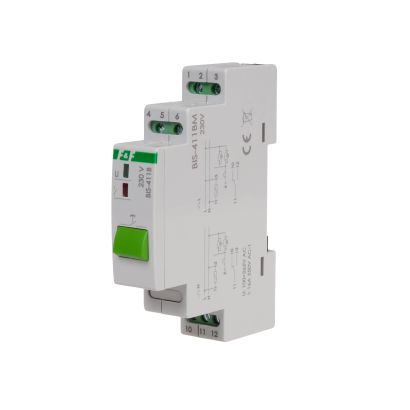
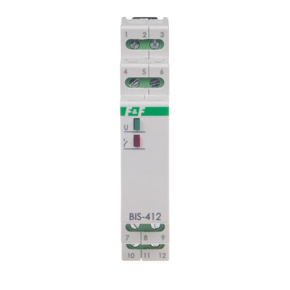
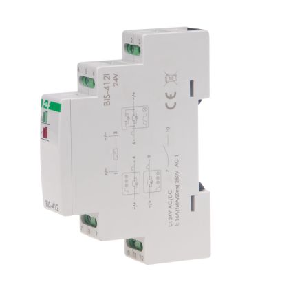
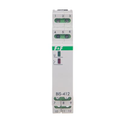
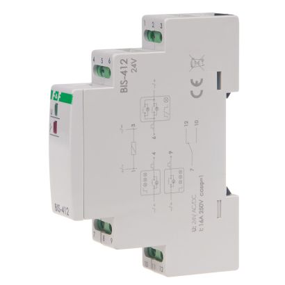
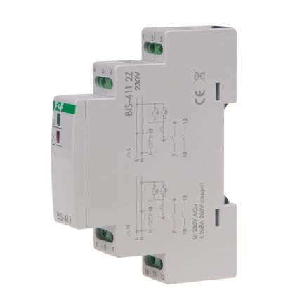
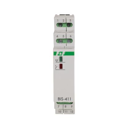
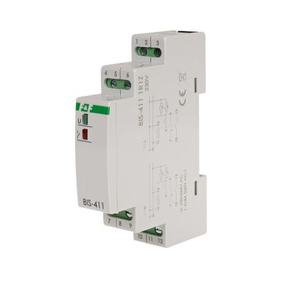
The relay power supply is indicated by a green LED U. Sequential relay has two separate outputs: R1 and R2. Contact status (closed/open) is forced sequentially in accordance with a predetermined program. Contacts switch to another state after subsequent pulse from control button. R1 and R2 contact activation is indicated by the relevant R1 and R2 red LED. After a power failure, state of the contact is reset. When the power is back on, the relay starts from the sequence number 0.
Attention!
The BIS-404 is compatible with bell pushes equipped with fluorescent lamps. ![]()
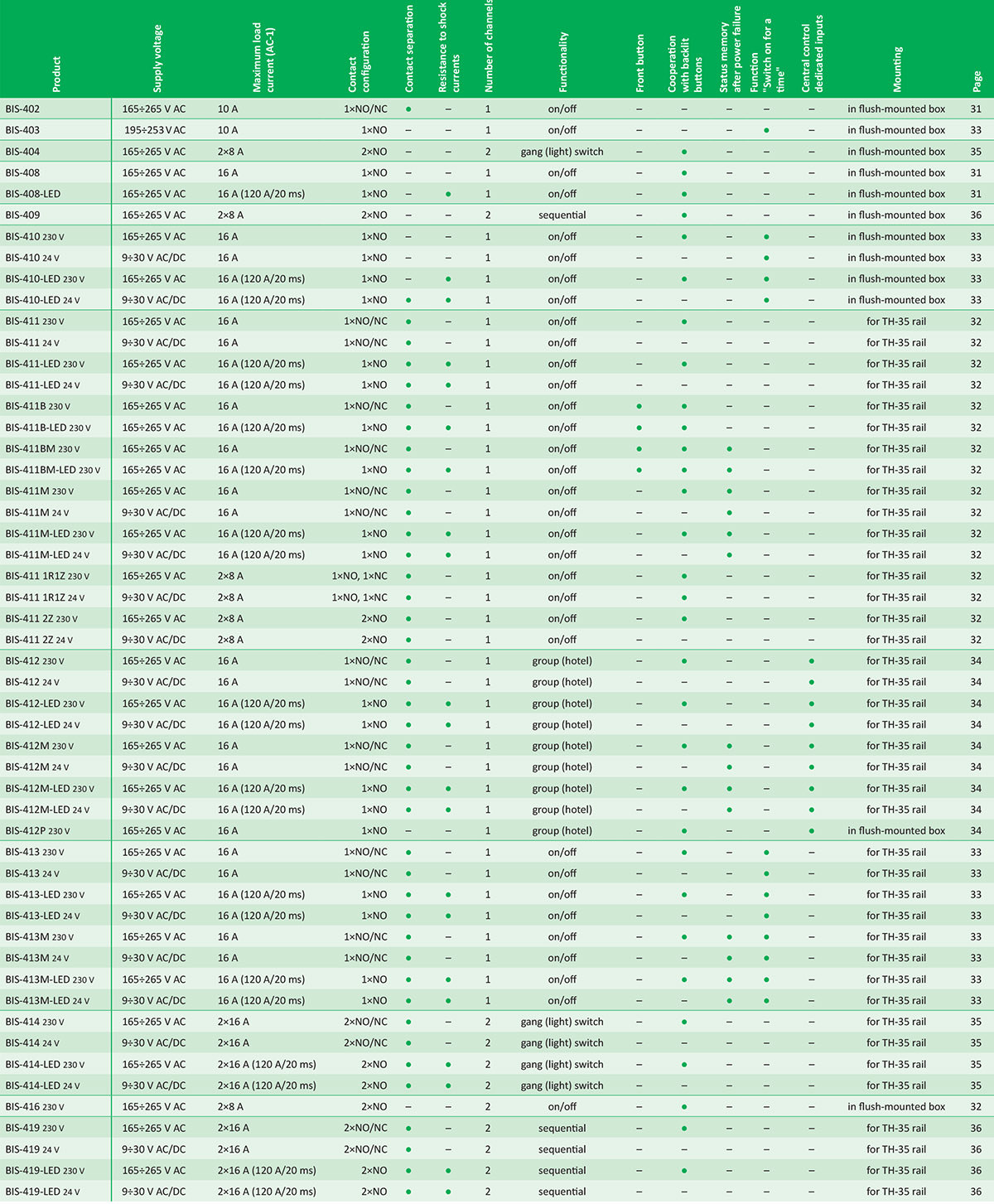
Power table
The above data are indicative and will depend to a large extent on the design of a specific receiver (especially for LED bulbs, energy saving lamps, electronic transformers and pulse power supplies), switching frequency and working conditions.