

Functioning
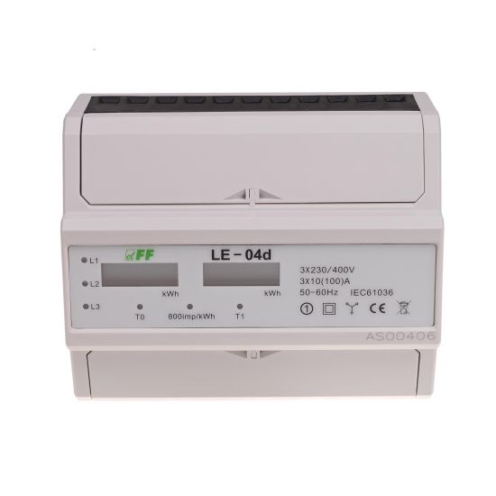
Special electronic system, under the influence of current flow and applied voltage, generates pulses in each phase in proportion to the electricity consumed in this phase. Energy consumption in phases is indicated by flashing LED A and C. The sum of the pulses of the three phases is indicated by flashing LED (800 pulses/kWh) and is converted to energy consumed in the entire three-phase system, and its value is displayed by segment LCD display.
The number after the decimal is tenths (0.11 kWh = 110 Wh).
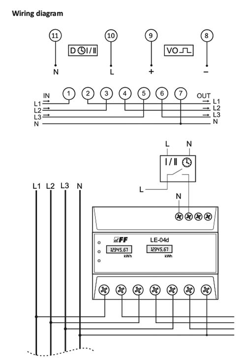
Indicator is suitable for registering the value of electricity in two-tariff system. Two separate displays T0 and T1 indicate the value of electricity consumption in a given tariff. Switching between the tariffs takes place when the control voltage is applied on the D input of the meter (terminals 10-11). This can done with external control clock. The T0 meter reads the value of energy consumption in the absence of control voltage at the input D. The T1 meter reads the value of energy from the appearance of the control voltage at the input D, until its disappearance. Operation of the given meter is indicated by appropriate LED.
Attention!
Indicator has a pulse output VO. This allows you to connect another pulse device that reads pulses generated by the meter. Connection of an additional device is not required for proper operation of the meter.
*) Base current - determines the current value at which the percentage measurement error is close to zero. If the current flowing through the meter is higher than the base current value, then the measurement error is negative, which works to the benefit of the electricity payer. On the other hand, if the current flowing through the meter is lower than the base current value, the percentage measurement error is positive and that acts against the electricity payer. These statements arise from metrological characteristics (percentage measurement error as a function of current), supplied to the user manual of a electricity meter. It is obvious that the meter measures electricity correctly with the meter accuracy class in the whole measurement range.
Maximum current - the maximum current for permanent load of the electricity meter.
Minimum current - the lowest value of the load current, which the meter detects and record.
Marking on the device: 10(100)A - position 1 (before the parenthesis): base current of 10A; position 2 (in parentheses): maximum current 100A.

