Polski
 English
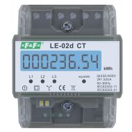
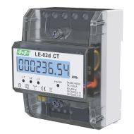
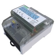
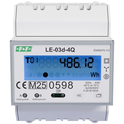
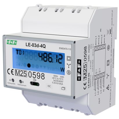
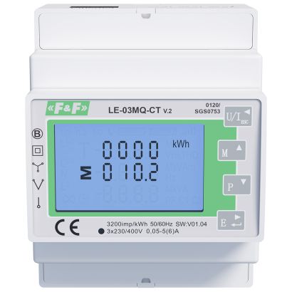
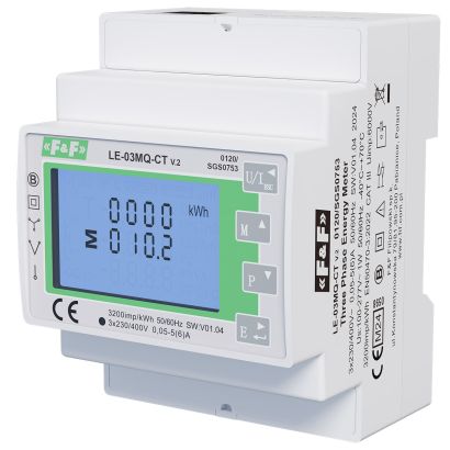
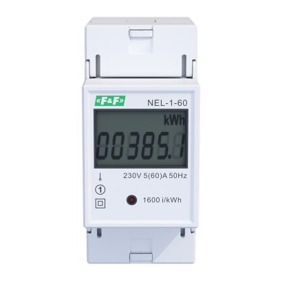
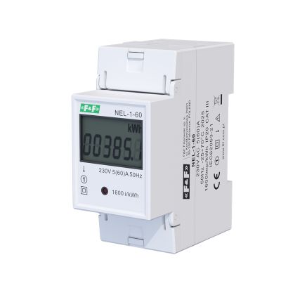
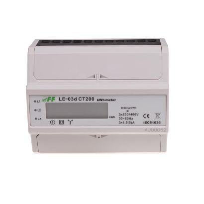
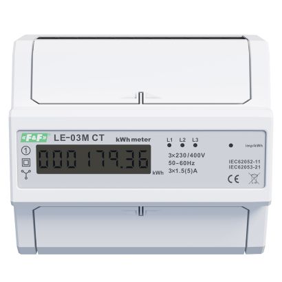
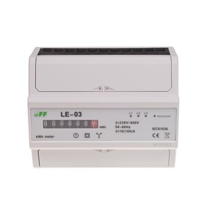
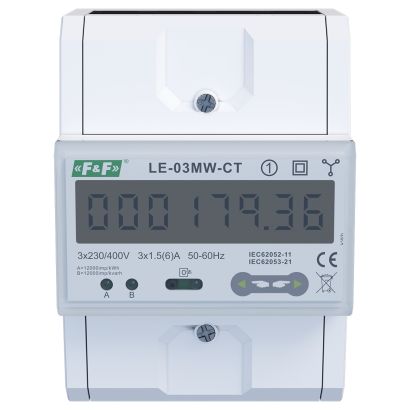
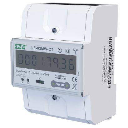
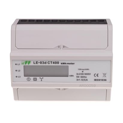
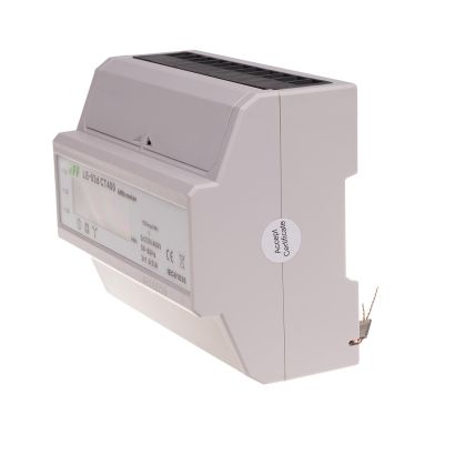
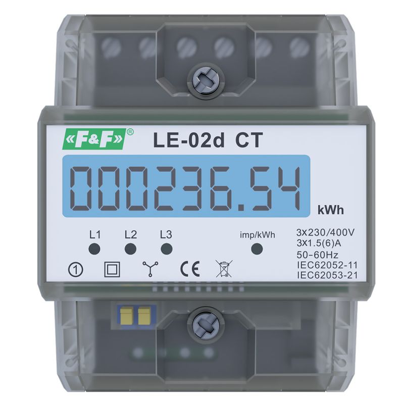
Three-phase type. With programmable current transducer ratio.
LE-02 CT is a static (electronic) indicator calibrated electricity three-phase alternating current system.

The electricity consumption meter is designed to work with current transformers with a primary current Ip in the range of 5–6000 A and a secondary current of 5 A. The maximum current measured by the system is determined by the primary current Ip of the current transformer used. The user can set the transformation ratio of the current transformers used in the meter, which allows the display of the actual amount of electricity consumed by the system.
Operation
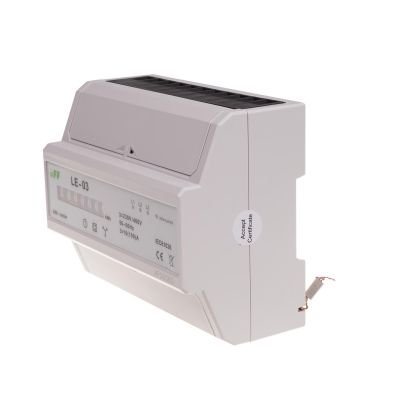
A special electronic circuit, under the influence of the flowing current and the applied voltage in each phase, generates pulses in a quantity proportional to the electrical energy consumed in that phase. Energy consumption in a phase is indicated by the flashing of the corresponding LED (L1, L2, L3). The sum of pulses from the three phases, indicated by the flashing of the LEDs, is converted into the energy consumed by the entire three-phase system, and its value is displayed on a segmented LCD display.
The meter’s memory stores the primary current values (Ip) of the transformers that can be used. Selecting the appropriate value corresponding to the connected transformers automatically sets the correct conversion factor, according to which the actual value of the system’s electricity consumption is calculated. The LCD display shows the actual value of the energy consumed in a format dependent on the selected transformer.
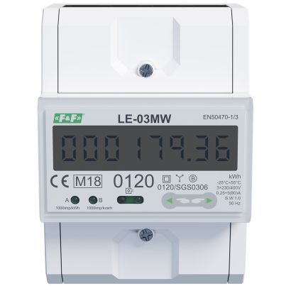
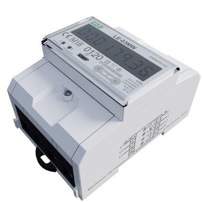
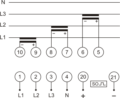
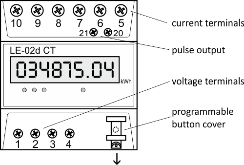
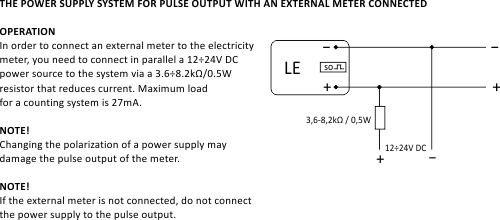
SO pulse output
The electricity consumption meterhas an SO+ - SO- pulse output. This allows the connection of a pulse counter that reads the pulses generated by the meter. No additional device is required for the meter to operate correctly. The meter’s pulse constant is 12,000 pulses/kWh for the maximum input current of the meter, i.e. the secondary current of the transformer (5A). When using dedicated current transformers, the number of pulses per 1 kWh is calculated using the formula (12,000 × 5)/Ip, where:
Ip – primary current of the transformers used.
Example:
for a 5/5 A transformer (Ip=5): (12,000 × 5)/5 = 12,000 pulses/kWh
for a 100/5 A transformer (Ip=100): (12,000 × 5)/100 = 600 pulses/kWh
Programming
The ratio can be programmed using a button located under the lower terminal cover of the meter.
Ip current values for the transformers stored in the meter’s memory:
5, 25, 40, 50, 60, 75, 80, 100, 120, 150, 200, 250, 300, 400, 500, 600, 800, 1000, 1200, 1500, 1600, 2000, 2500, 3000, 4000, 5000, 6000.
Pressing the programming button again moves to the next value.
Once you have reached the desired value, hold the button for >30s to confirm your selection.
The procedure for resetting the gearbox is described in the meter’s user manual.
Data format
Data display format depending on the gear settings:
| Format | Current Ip |
| 000000.00 | 5; 25; 40; 50; 60 |
| 0000000.0 | 75; 80; 100; 120; 150; 200; 250; 300; 400; 500; 600 |
| 00000000 | 800; 1000; 1200; 1500; 1600; 2000; 2500; 3000; 4000; 5000; 6000 |
The meter features sealable input and output terminal covers to prevent tampering.

Three-phase type. With programmable current transducer ratio.
LE-02 CT is a static (electronic) indicator calibrated electricity three-phase alternating current system.