Polski
 English


Features
* 1 NO/NC separated contact
* ON / OFF control
* output status
* timer control options:
- delayed activation
- delayed activation for a preset time
- cyclic operation ON / OFF
- cyclic operation OFF / ON
* state memory state after power outage
* automatic start for time function
* time of the last output switching
* number output switching
* number of executed cycles for time functions
Functioning
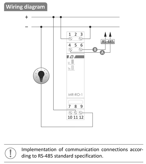
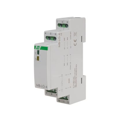
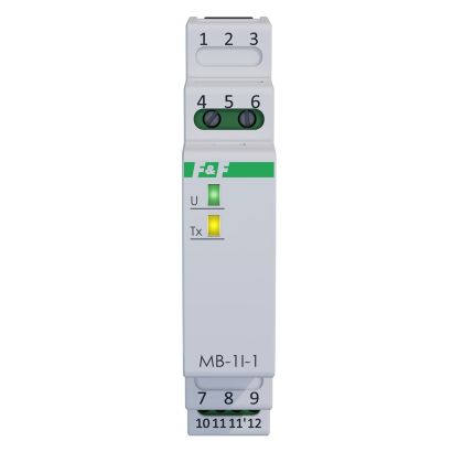
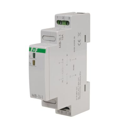
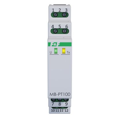
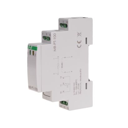
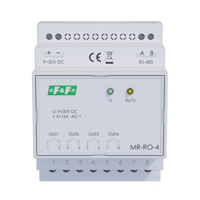
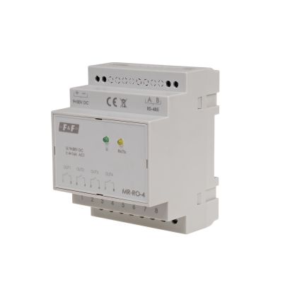
The MR-RO-1 module is equipped with a controllable relay output (separated contact). The output operates according to the preset mode of operation and parameters assigned to it. The setting and reading the output status, operation parameters and adjustment of all communication and data exchange parameters is carried out via RS-485 port using MODBUS RTU communication protocol. Power is indicated by a green LED U light. Correct data exchange between the module and other device is indicated by the LED yellow Tx light.
OPERATION MODES
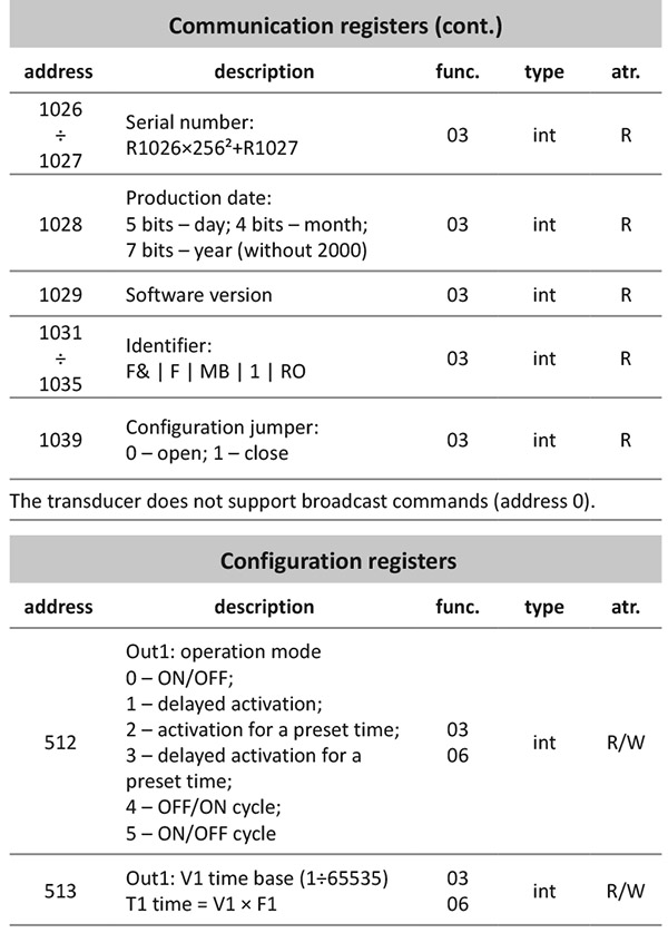
0. ON/OFF
The default mode of module operation in which the output is directly switched on and off using commands sent via Modbus.
![]()
1. Delayed activation
Upon receiving of the ON command, the controller measures the time set in parameter T1 and activates the relay. The relay will shut down after receiving the OFF command. Sending the OFF command during the T1 time countdown will abort the cycle. Another ON command received at the time T1 or when the relay is already switched on will be ignored.
2. Activation for a preset time
The relay activates after receiving the ON command, and deactivates when the preset time is up. Next cycle can be initiated by sending the next ON command. Sending the OFF command turns off the relay. The ON command received during T1 time will be ignored.
3. Delayed activation for a preset time
The module starts measuring time T1 after receiving the ON command and then closes the relay for a time T2, after which the relay is switched off. Next cycle after completing the previous one can be activated by sending another ON command. Sending the OFF command OFF breaks the execution of the cycle and turns off the relay. The ON command received during cycle execution will be ignored.
4. OFF/ON cycle
Cyclic operations OUT OFF (relay off) for the time T1 and OUT ON (relay on) for the time T2. The cycle is started by sending the ON command. The number of executed cycles depends on the 0x235 registry value. If this register is set to 0, the program will be executed cyclically until the OFF command is sent. If this registry value is other than zero (max. 65 535), the controller performs a predetermined number of cycles, then turns off. Sending the OFF command during the cycle breaks its execution and turns off the relay. The ON command received during cycle execution will be ignored. After the programmed number of cycles the next ON command starts the program from the beginning.
5. ON/OFF cycle
Cyclic operations OUT ON (relay on) for the time T1 and OUT OFF (relay off) for the time T2. The cycle is started by sending the ON command. The number of executed cycles depends on the 0x235 registry value. If this register is set to 0, the program will be executed cyclically until the OFF command is sent. If this registry value is other than zero (max. 65 535), the controller performs a predetermined number of cycles, then turns off. Sending the OFF command during the cycle breaks its execution and turns off the relay. The ON command received during cycle execution will be ignored. After the programmed number of cycles the next ON command starts the program from the beginning.
STATE MEMORY AND AUTOMATIC START
The active memory of the state restores the state of the program from before the power outage when the power is back on. State memory sets the contact in position from before the power outage for the 0 mode. Setting the state memory for modes 1-5 means that if at the time of the power outage the program was in progress, then when the power is restored it will be launched from the beginning.
Active automatic start function (only if the state memory function is inactive) is the automatic execution of the selected operating mode after switching on the power supply of the module.