 Polski
 English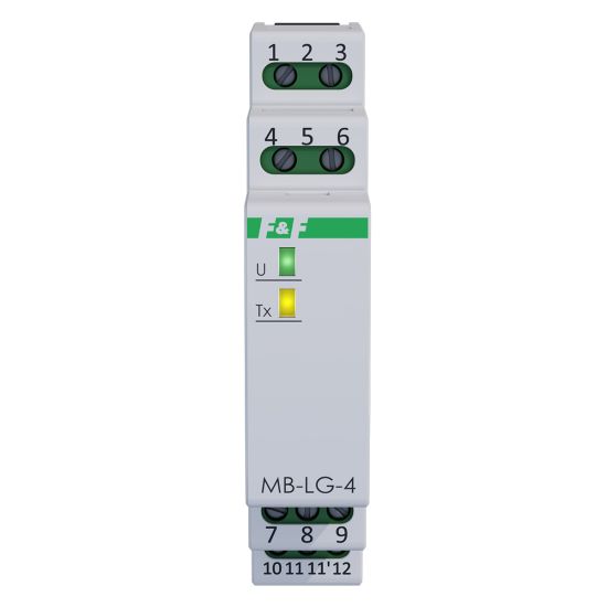
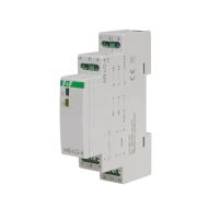
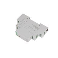
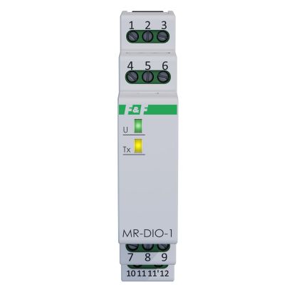
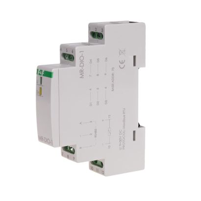
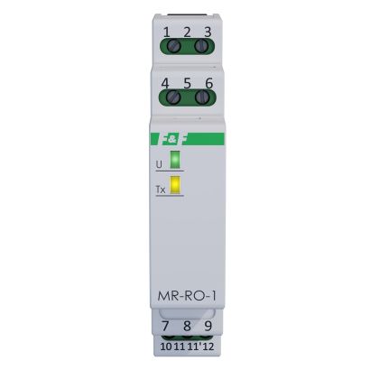
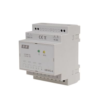
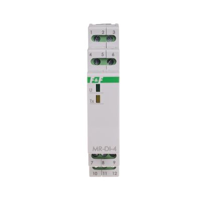
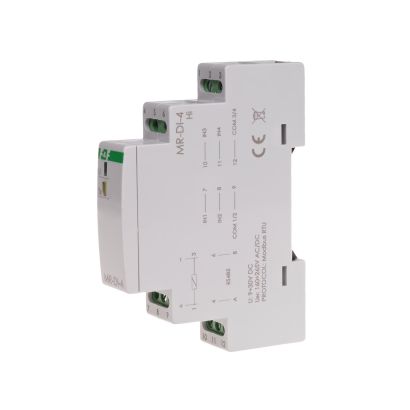
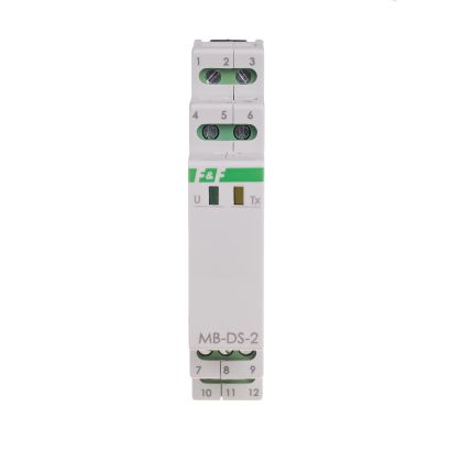
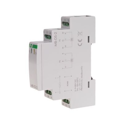
4-channel operating time counter with high-voltage counting inputs and Modbus RTU communication.
4 independent counting inputs.
Input voltage range: 160–265 V AC/DC.
Input time filter.
Counter status memory in the event of a power failure.
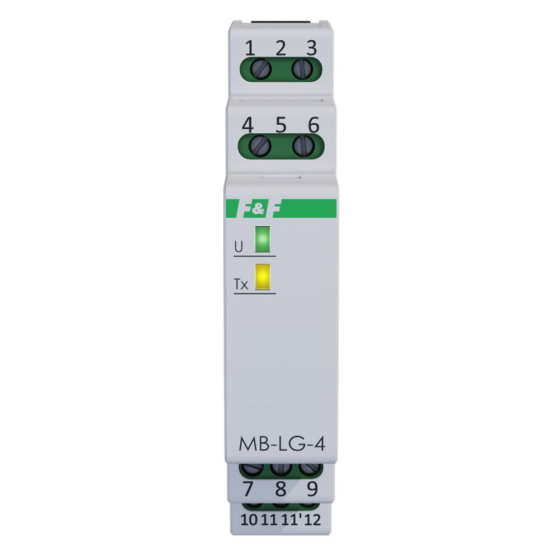
The MB-LG-4 Hi is a four-channel operating time counter designed to work with high-voltage input signals. The recorded data is accessible via Modbus RTU.
Operation
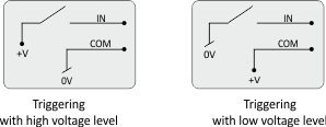
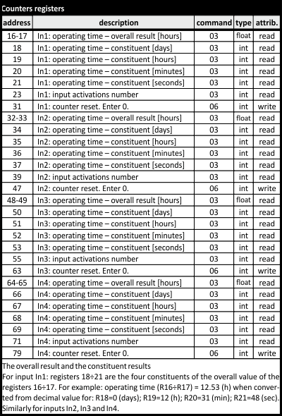
The MB-LG-4 operating time counteris a 4-channel unidirectional counter. Each channel is independent and counts operating time according to individual settings. The result is displayed as a floating-point number and, in parallel, as integer values broken down into days, hours, minutes and seconds. The counter has a software function enabling the counter status of each channel to be reset independently. The maximum count is approximately 150 years. Upon reaching the maximum count (overflow), the counter automatically resets and starts counting from 0. The module features configurable options for counting using a low (0V) or high (V+) signal, as well as a closed or open input signal circuit. The counter allows you to set the minimum duration of an input signal that will be detected at the input and treated as an input activation (time filter). Shorter signals are ignored. This serves to eliminate interference (spurious pulses) that may occur at the input.
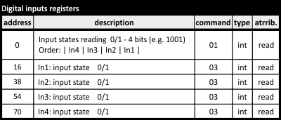
The counting input can be used as a digital input (DI) with the option to read its status.
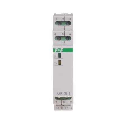
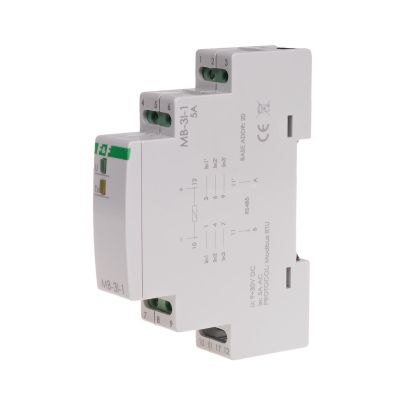
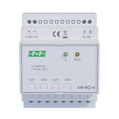
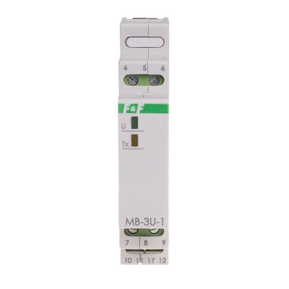
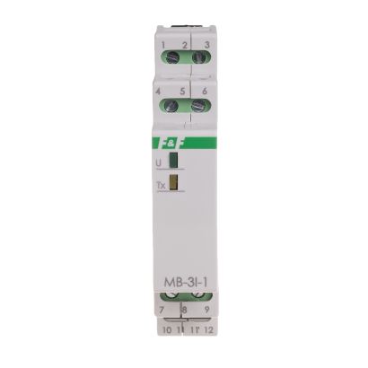
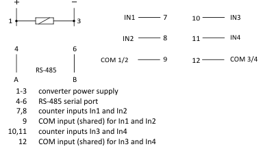
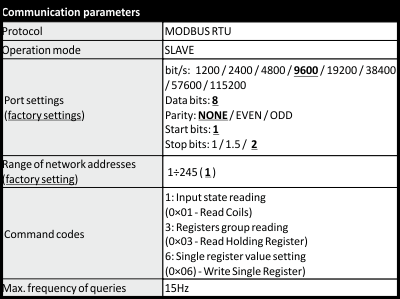
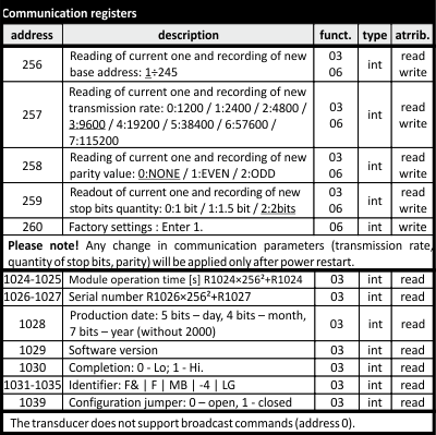
Reading of count values and setting of all counting, communication and data exchange parameters are carried out via the RS-485 port using the MODBUS RTU communication protocol. The application of supply voltage is indicated by the green U LED lighting up. Successful data exchange between the module and another device is indicated by the yellow Tx LED lighting up.
MB Config
The programme enables test readings and the configuration of the converter’s communication and configuration parameters.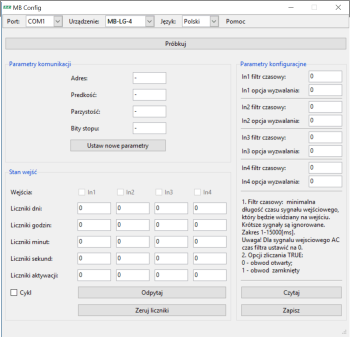
Communication between the module and a PC via theCN-USB-485 USB converter
Free software.

MODBUS RTU Communication parameters
4-channel operating time counter with high-voltage counting inputs and Modbus RTU communication.
4 independent counting inputs.
Input voltage range: 160–265 V AC/DC.
Input time filter.
Counter status memory in the event of a power failure.