 Polski
 English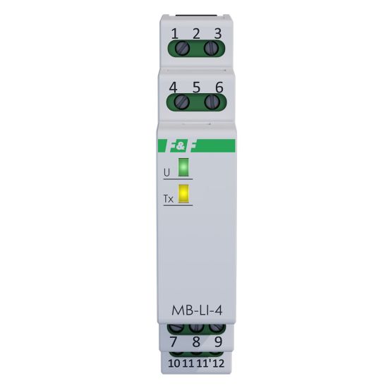
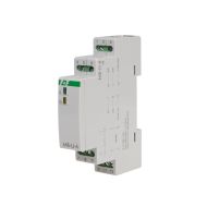
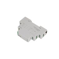
4-channel pulse counter with high-voltage counting inputs and Modbus RTU communication
4 independent counting inputs.
Counting input voltage range: 160–265 V AC/DC.
Maximum counting frequency: 100 Hz.
Programmable conversion factor.
Counter status memory in the event of a power failure.
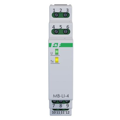
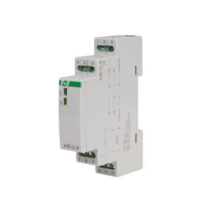
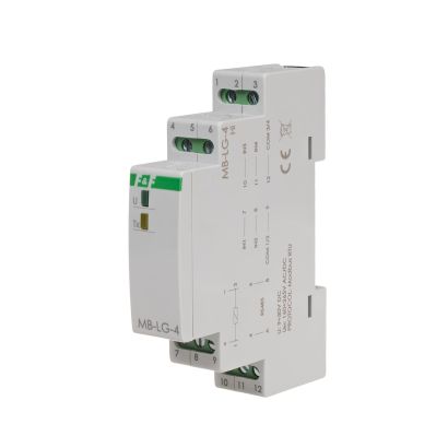
The MB-LI-4 Hi is a four-channel pulse counter with high-voltage counting inputs. It counts AC/DC signals generated by external devices and provides the results via Modbus RTU.
The MB-LI-4 module is a 4-channel, unidirectional pulse counter. Each channel is independent and counts pulses according to its individual settings. The results are presented as the number of pulses and a rescaled value in the range from 0 to ~4.29 billion. The counter has a software function that allows the counter status of each channel to be reset independently. Upon reaching the maximum number of pulses (overflow), the counter automatically resets and starts counting from 0. The module features configurable options for counting pulses with a low (0 V) or high (V+) signal, and with a rising or falling edge.
Additionally, the counting input can be used as a digital input (DI) with the ability to read its status.
Reading the count of pulses, scaled values, and setting all counting, communication and data exchange parameters is carried out via the RS-485 port using the MODBUS RTU communication protocol.
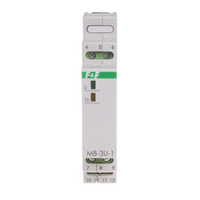
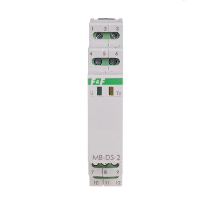
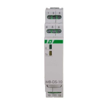
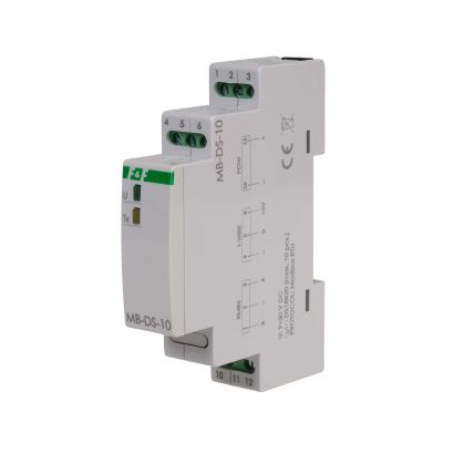
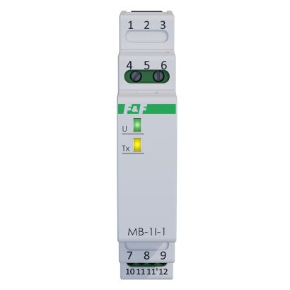
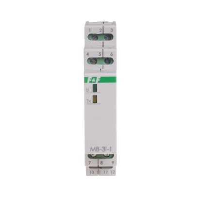
The application of supply voltage is indicated by the green U LED lighting up. Successful data exchange between the module and another device is indicated by the yellow Tx LED lighting up.
NOTE!
An external control voltage is always required to trigger the input. If the module’s supply voltage is used for this purpose, this results in the loss of galvanic isolation between the control inputs and the power supply and communication circuits.
MB Config
The programme allows you to test-read values and configure the transducer’s communication and configuration parameters.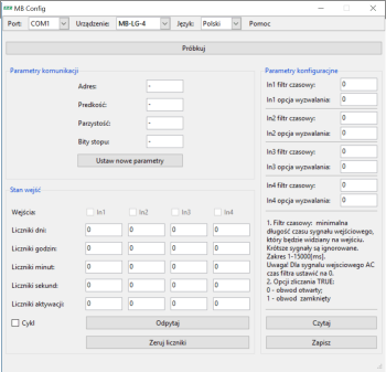
Communication between the module and a PC via theCN-USB-485 USB converter
Free software.

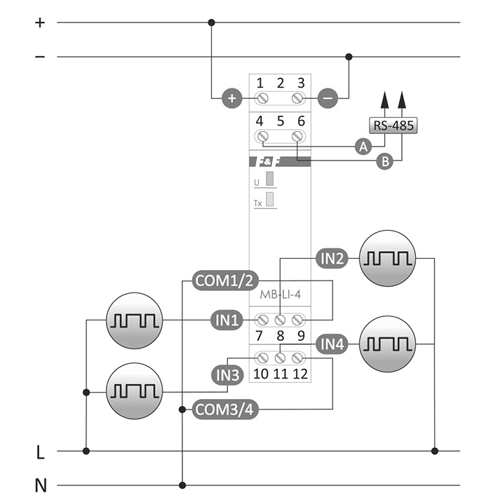
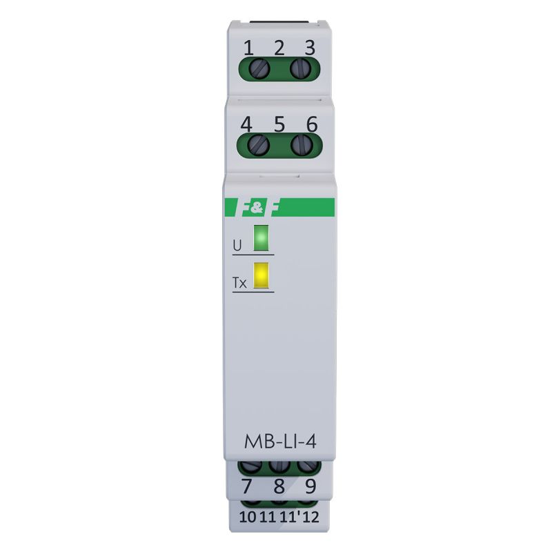
4-channel pulse counter with high-voltage counting inputs and Modbus RTU communication
4 independent counting inputs.
Counting input voltage range: 160–265 V AC/DC.
Maximum counting frequency: 100 Hz.
Programmable conversion factor.
Counter status memory in the event of a power failure.