 Polski
 English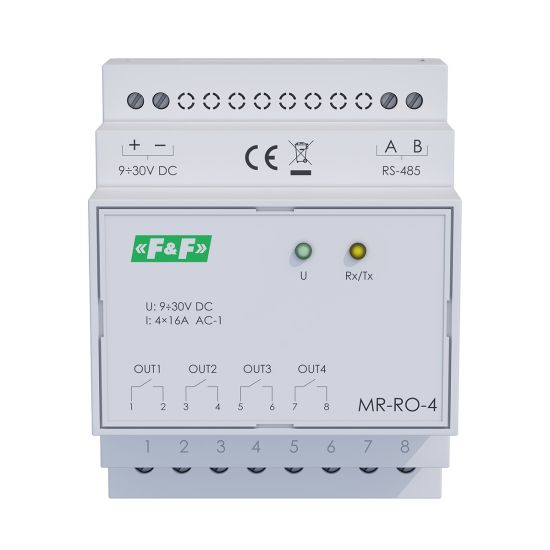
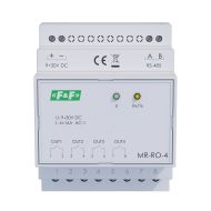
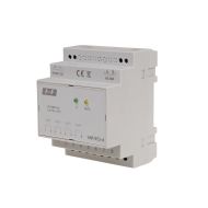
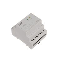
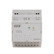
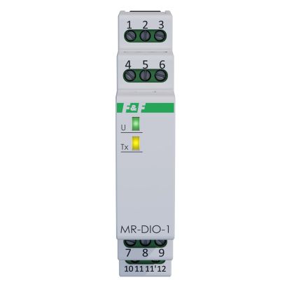
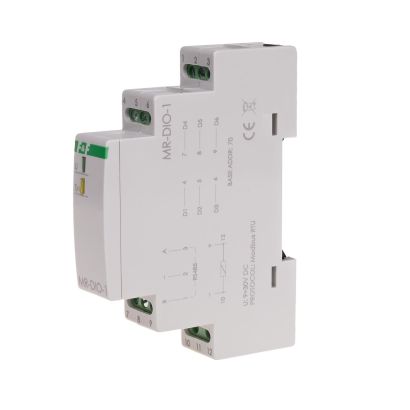
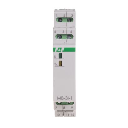
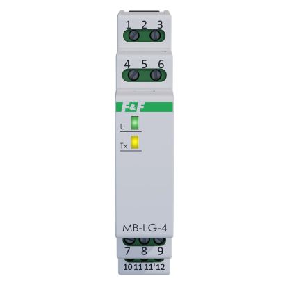
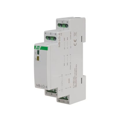
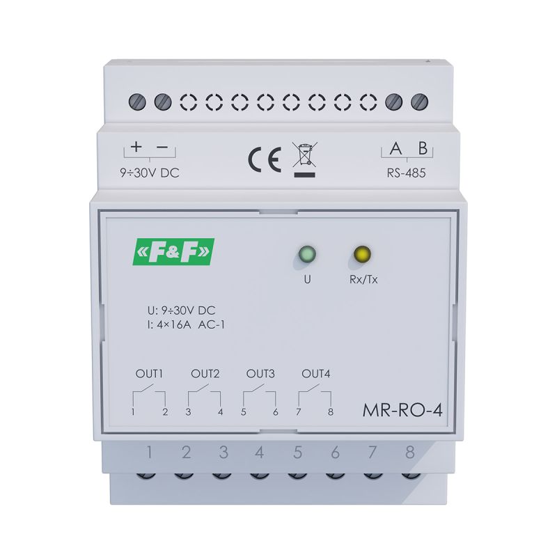
Module with 4 independent relay outputs and Modbus RTU communication
4 controllable relay outputs with isolated contacts.
ON/OFF control.
Timing functions.
Power-fail state retention.
Communication interface: RS-485.
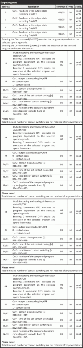
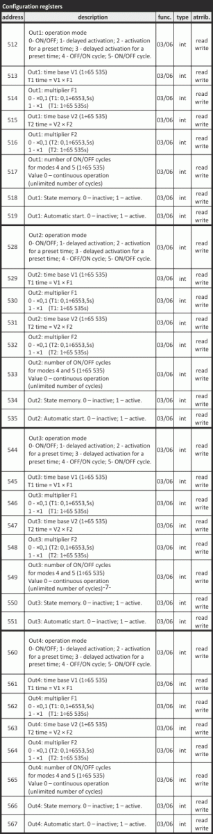
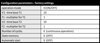
The MR-RO-4 extends the system with four independently controlled relay outputs. Each output can operate according to its own mode and parameters set via Modbus RTU.
OPERATING MODES
0. ON/OFF (on/off)
The module’s default operating mode, in which the output is switched on and off directly via commands sent over Modbus.

1. Delayed activation

Upon receiving an ON command, the controller counts down the time set in parameter T1 and activates the relay. The relay will deactivate upon receiving an OFF command. Sending an OFF command whilst the T1 countdown is in progress will interrupt the cycle. Any subsequent ON command received during the T1 time period or whilst the relay is already energised will be ignored.
2. Activation for a set duration

Upon receipt of an ON command, the relay switches on, and switches off after the set time has elapsed. Once the set time has elapsed, the cycle can be restarted by sending another ON command. Sending an OFF command causes the relay to switch off. An ON command received whilst the T1 time is being counted down will be ignored.
3. Delayed activation for a set time

Upon receiving an ON command, the module counts down the time T1, then closes the relay for a time T2, after which the relay is de-energised.
Once a full cycle has been completed, the next cycle can be initiated by sending another ON command. Sending an OFF command interrupts the cycle and deactivates the relay. Any ON command received whilst the programme cycle is in progress will be ignored.
4. OFF/ON cycle

Cyclical execution of the OUT OFF operation (relay de-energisation) for a duration of T1, followed by the OUT ON operation (relay energisation) for a duration of T2. The cycle is initiated by sending an ON command. The number of cycles performed depends on the value set in register 0x235. If this register is set to 0, the programme will run cyclically until an OFF command is sent. If this register is set to a value other than zero (max. 65535), the controller will execute the specified number of cycles and then switch off.
Sending an OFF command whilst the cycle is running will interrupt its execution and deactivate the relay. Whilst the cycle is running, any subsequent ON command will be ignored. Once the programmed number of cycles has been completed, the next ON command will restart the programme from the beginning.
5. ON/OFF cycle

Cyclical execution of the OUT ON operation (switching the relay on) for a duration of T1 and the OUT OFF operation (switching the relay off) for a duration of T2. The cycle is started by sending an ON command. The number of cycles performed depends on the value set in register 0x235. If this register is set to 0, the programme will run cyclically until an OFF command is sent. If this register is set to a value other than zero (max. 65535), the controller will execute the specified number of cycles and then switch off.
Sending an OFF command whilst a cycle is in progress interrupts its execution and deactivates the relay. Whilst a cycle is in progress, any subsequent ON command will be ignored. Once the programmed number of cycles has been completed, the next ON command will restart the programme from the beginning.
STATE MEMORY AND AUTOSTART
For each of the outputs, it is possible to activate special status memory and autostart functions.
When power is restored, active state memory restores the programme to the state it was in before the power failure. For mode 0, this sets the contact to the position it was in before the power failure; for modes 1–5, enabling state memory means that if the programme was running at the time of the power failure, it will restart from the beginning once power is restored.
The active autostart function – only when the state memory function is inactive – automatically initiates the selected operating mode upon power-up of the module.
MB Config
The programme enables test readings of values and the configuration of the module’s communication and configuration parameters.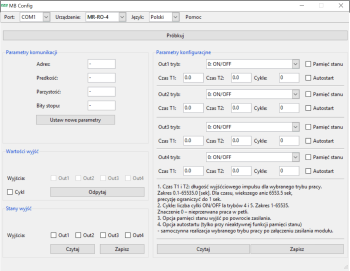
Communication between the module and a PC via theCN-USB-485 USB converter
Free software.


Module with 4 independent relay outputs and Modbus RTU communication
4 controllable relay outputs with isolated contacts.
ON/OFF control.
Timing functions.
Power-fail state retention.
Communication interface: RS-485.